- DESCRIPTION
Description
The EM model A20a is a very sensitive amplifier for making sub-nano-volt measurements and is designed to be used in calibration, cryogenic research and instrumentation systems.
The A20a has been produced in response to requests for an amplifier of similar sensitivity to those used in EM null detectors, having a very low short circuit input equivalent noise resistance of less than 10Ω, giving resolution of a hundred picovolts with comparatively short response time.
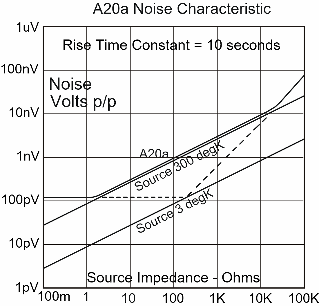
Particular care has been taken with respect to the range of source resistance with which the A20a can operate. This parameter is very important when measuring cryogenic sources. A study of the graph overleaf of source resistance against noise voltage will show the importance of this. The ‘voltage’ and ‘current’ noise lines have been extrapolated from 300 deg K to 3 deg K. and it can be seen that the A20a, while remaining at room temperature can efficiently measure a source at helium temperature, without adding significantly to the overall noise.
There are 4 gain settings from a thousand to a million and these are selected by voltage levels applied via the 25 way `D’ type connector, which has a control for a filter, as well as carrying the output connection, the power supply and other functions. It is possible to have user defined gain settings if required, in which case the gain determining resistors are mounted externally and are under the user’s control. The four gain control pins are left open circuit and the gain resistor is connected between pins 10 and 11 on the ‘D’ connector.
Controls are accessible at the edge of the case for nulling offset voltage and current.
The input connections are made on copper terminals with nuts and washers all made from the same high purity copper, so that thermal emf is minimised.
The A20a is mounted in a heavy duty mumetal case, and the input unit is enclosed in double screens of heavy gauge mumetal.
- SPECIFICATION
Specification: DC Nanovolt Amplifier Model A20a
Noise
Equivalent noise resistance less than 3Ω. Noise voltage depends on bandwidth e.g. rise time constant 10 seconds gives peak to peak noise voltage of 140 picovolts.Offset Voltage
Adjustable to zero by a ten turn potentiometer accessible at the the edge of the case. Temperature coefficient better than 300pV per degree C.Offset Current
Adjustable to zero by a ten turn potentiometer accessible at the edge of the case. Temperature coefficient better than 10pA per degree C.Gain
There are 4 gain settings 1K, 10K, 100K, and 1M. These gains are set internally.
Accuracy 0.02%, subject to noise floor.
Temperature coefficient 5ppm per degree C.Filter
A filter may be selected which gives the following rise time constants.
Range Time Constant
1K: No Increase
10K: 100 milliseconds
100K: 1 second
1M: 10 secondsInput Impedance
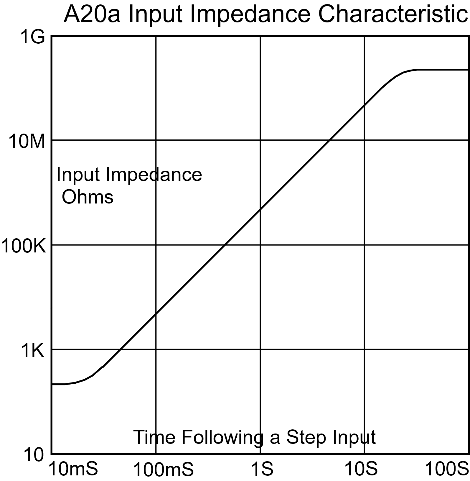
Greater than 30MΩ, 3 seconds after an input step
increasing with time to 1GΩ, see input impedance graph.Source Resistance
The A20a closely follows the source thermal noise characteristic with sources resistances of 3Ωup to around 50KΩ. With source resistances below 3Ω, the noise is substantially constant down to zero ohms. Above 50KΩ, the noise voltage increases over the thermal noise characteristic by about 10 dB per decade of source resistance. The input noise characteristic graph shows that, if thevoltage' andcurrent’ noise lines are extrapolated as far as the thermal noise line for helium temperature, the A20a still adds insignificantly to the total noise at around 1K source impedance.Input Level
The A20a will accept input voltage up to 2mV. Input voltage up to 2 volts will not cause damage, but if the input is saturated for any length of time, there may be a thermal offset, which could take time to reduce to sub nanovolt levels.Output Level
The A20a will provide an output of plus or minus 3 volts and can drive loads of up to 5mA.Connectors
The input connectors for the A20a are pure copper terminals with nuts and washers made from the same material. The threads are 2BA (4.8mm diameter). Input connections should be made using low thermal emf untinned copper wire. In practice, new, unbent transformer wire, carefully stripped of insulation, is satisfactory.D25 Plug Connection
Pin Number Function Input/Output 1 Filter +5v DC 2 1M Gain +5v DC 3 100k Gain +5v DC 4 10k Gain +5v DC 5 1k Gain +5v DC 6 0v 0v 7 Supply Negative -5v DC 8 Supply Positive +5v DC 10 Direct Output Output 11 Feedback 15 Filtered Output Output 18 Signal 0v 19 Case The plug outer shield is connected to the A20a case.
Isolation between case and 0v. 10GΩ minimum.
For control of gain and filter functions, the appropriate pin should be connected to + 5 volts.
All unused pins should be left open circuit.Power Supply
Minimum +/- 5.5 volts. Maximum +/- 8 volts.
Nominal supply voltage +/- 6 volts
Current requirement 2 milliamps quiescent.
This may increase up to 5 milliamps when the amplifier sees a full scale input on the 1K rangeFixing
4 holes required M4 centres 8.4 inches by 5.6.inches.Dimensions and Weight
Length 8.75 inches (222mm)
Width 6 inches (152.4mm)
Depth including terminals 3.7 inches (95mm)
Weight 9 lbs (4 Kg) - GRAPHS


