Please note that we have temporarily suspended production of this model.

- DESCRIPTION
Description
The EM DC Picovoltmeter Model P13a is an ultra sensitive instrument which can amplify and measure DC potential down to about 20 picovolts (2 X 10e-11 volts).
It is ideal for use as a null detector for low impedance bridge balancing.
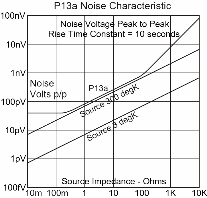
The noise performance is such that, using a source impedance of 0.25 ohm or higher, the detection level will be limited by the Johnson noise of the source. The equivalent noise resistance of the P13a is only 250 milli-ohms. To make full use of the noise performance, it is desirable to use it with low source impedance. While the P13a can be operated with source impedance of 10K ohm or more, its characteristic will be overwhelmed by the source noise if the source impedance is too high. Great care must be taken with the input leads and connections, to keep their resistance below the equivalent noise resistance of the instrument if possible.
In order to realise ultra low detection levels, the drift characteristics with temperature and time have to be maintained to levels which have been hitherto unattainable.
The design of the P13a ensures that, even in normal laboratory environments, the lower ranges are easy to use.
The excellent stability of this instrument means that it is deal for long term drift measurements, and may be coupled to a recorder and left unattended for long periods.
A six position filter gives the user control over the response time and reduction of noise from the circuit being measured.
A calibrated offset voltage control is provided with an eleven position multiplier switch, giving a maximum offset of plus and minus 100 micro-volts. This can be used to measure small changes in comparatively large signals. The level of input which can be offset on any range will be limited only by the resolution of the calibrated potentiometer, i.e. about 0.01%.
The pure copper input terminal arrangement, with shield, allows easy connection to the circuit to be measured.
A second input is provided, in conjunction with a switch on the front panel, which decreases the sensitivity of the basic ranges by one million times.
There are two outputs at the rear of the instrument, one direct and the other isolated. The direct output is used where maximum linearity is required although the isolator also has good linearity.
The instrument is battery operated from internal chargeable batteries and so has the advantage of complete isolation. There are two modes of battery charging.
The instrument may be connected to the mains supply and use the specially designed multiple screened toroidal mains transformer, or a separate connector is provided so that an external current generator may be used to maintain the battery charge. The latter mode may be useful when long term resolution of small signals is required.
The P13a is engineered to a very high standard and comes complete with a terminal shield, which simply plugs onto the two outer front terminals.
- SPECIFICATION
Specification: D.C. Picovoltmeter Model P13a
Range
Input 1. 12 basic ranges. +/- 1nV fsd to +/- 300uV fsd.
Input 2. +/- 1mV fsd to +/- 300V fsd. via X 1M attenuatorAccuracy
Direct Output. +/- 0.5%
Isolated Output. 1%
Meter +/- 2% fsd.
Attenuator +/- 0.5%Zero Drift
Better than 300pV per degree C.
Noise
Equivalent noise resistance less than 250 milli-ohms.
Peak to peak noise voltage depends on filter setting e.g. filter time constant 30 seconds gives peak to peak noise voltage of approximately 24 picovolts with short circuit input.Source Resistance
Up to 1 K ohm.
The full potential of the noise performance of the P13a will be realised at low source impedance, less than or comparable with the enr.Resolution
Better than 20 Pico volts, dependent on response time.
Input Impedance
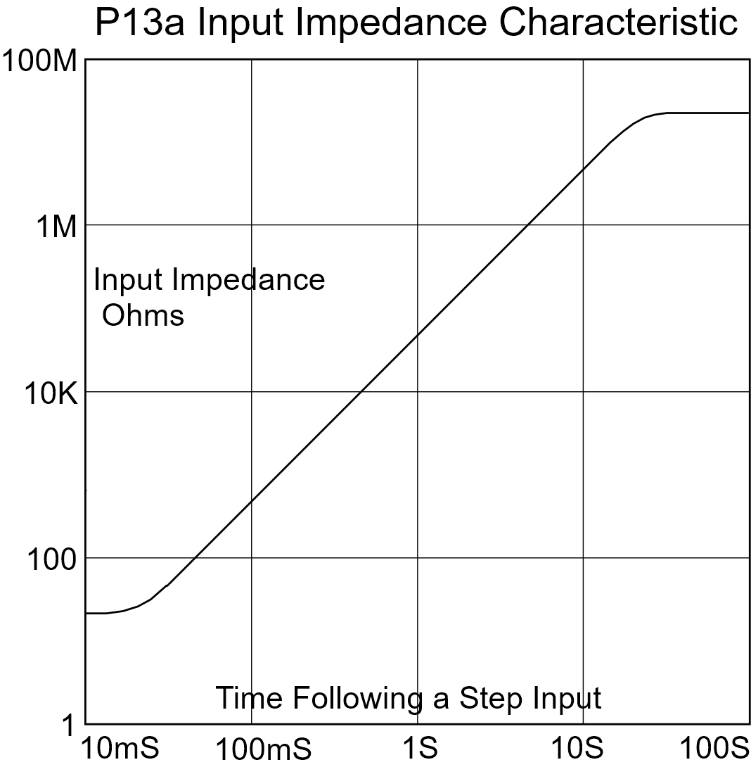
Input 1. Approximately 1 M ohm, 3 seconds after a step change in the input increasing with time to more than 100 M ohm.
Input 2. 10 M ohm.Offset Current
Adjustable to zero at the front panel.
Temperature coefficient better than 20pA per degree C.Response Time
Depends on setting of filter and range. Minimum 100 milliseconds. Maximum 50 seconds.
Filter
Six position low pass filter operated by a switch on the front panel.Offset
10 turn potentiometer with dial, calibrated 0-100 on the front panel, in conjunction with an eleven position switch giving maximum offsets of plus and minus 10nV, 100nV, 1uV, 10uV, 100uV, and a ‘0’ position. Resolution better than 0.01%. Accuracy better than 1%.Series Mode Rejection
Greater than 80dB at 50Hz.
Common Mode Rejection
Greater than 180dB at 50Hz (output to Input)Outputs
Direct and Isolated outputs giving 0 to +/- 1V for full scale deflection.
Amplifier gain equals the reciprocal of the range setting in volts.Isolation
Input to case. 100 G ohm.
Input to output. 100 G ohm shunted by 1pF unbalanced capacity.Connectors
Inputs. Low thermal emf pure copper terminals for basic ranges (Input 1) with plug on terminal cover.
‘Input 2’ and ‘Case’. 4mm terminal sockets.
Outputs 4mm sockets at rear panel.Meter
Taut band movement type.
100mm Mirror Scale Calibrated 10-0-10 and Rt10-0-Rt10.
Power Supply
Internal rechargeable batteries giving 100 hours operation from a full charge. Internal mains powered charger fully charges the batteries in 20 hours with the instrument switched off or 24 hours when in use. Power required 110V or 240V. 50Hz or 60Hz 5VA.
There is an alternative input to the batteries to charge from an external current source. Minimum voltage 20V
Battery capacity 2Ah.
NB. External charger must be a current source.Dimensions
Width 314 (12.4″)
Depth 322 (12.7″)
Height 179 (7″) Including folded feet.
Weight
31 lb. (14Kg). - GRAPHS


