- DESCRIPTION
Description
The EM DC Amplifier model A22 is a low noise amplifier module for sensitive DC measurements, data collection and systems, and is ideal for very sensitive temperature measurement using thermocouples.
The noise level of the A22 is equivalent to a perfect resistor of about 150 ohms.
When used with normal type thermocouples for temperature measurement, sensitivities of around 20 micro-Kelvin can be achieved. The input voltage drift is very low and is compatible with voltage sensitivities of about 1 nanovolt.
The A22 has many other features desirable in a measurement amplifier. The very high loop voltage gain of 100T, or 280dB, means that high overall gain may be used, controlled precisely by feedback resistors, thus ensuring good linearity, with the accuracy defined by the feedback resistors used.
Despite the high gain, the model A22 is stable with 100% feedback, thus allowing feedback capacitors to be used to filter the output. The input signal level can be up to plus or minus 20 milli-volts and the output can be up to plus and minus 3 volts.
The response time of the A22 is fast, and the gain is reduced to unity at about 20 kHz, thus ensuring good response times, even at high gain settings.
The power supply requirement is low, being about 1.2 milli-amps with power supplies of plus and minus 6 volts, making it ideal for multi-channel measurement systems.
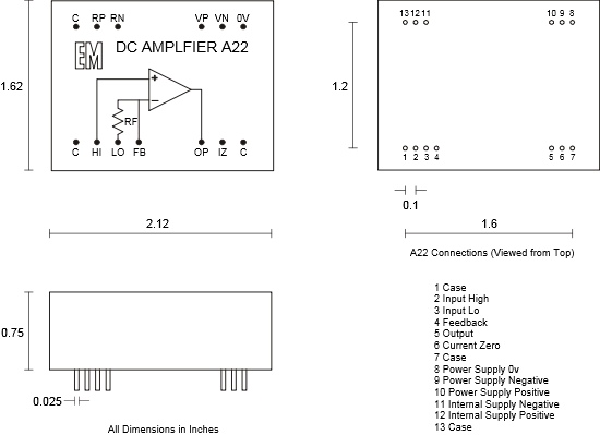
The A22 is designed to be mounted on a printed circuit board, using a 0.1” grid, with 13 pin connections on a rectangle 1.6” X 1.2”, and is built into a heavy gauge mumetal case which gives it very good magnetic, electrostatic and thermal immunity from interference. A printed circuit board is available which provides connections for power supply, gain, filter capacitors and outputs. It also contains controls for voltage and current offsets, power supply de-coupling and a passive output filter to reduce any modulation by-product.
- SPECIFICATION
Specification: DC Amplifier Model A22
Noise
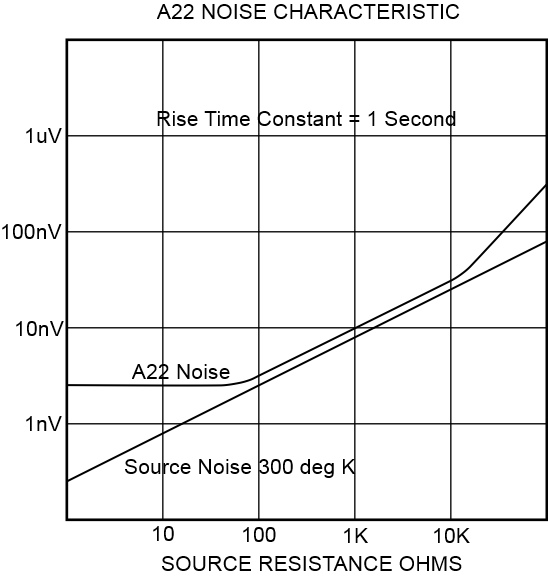
Equivalent noise resistance approximately 150 ohms. Peak to peak noise voltage depends on bandwidth selected e.g. rise time constant 1 second, peak to peak noise voltage is approximately 3 nano-volts with the rms equivalent being about 600 pico-volts.Offset Voltage
This is adjustable to zero by introducing a current into the feedback terminal. The internal feedback resistor is 10 ohms and so an adjustment current of plus and minus 10 nano-amps will give a voltage offset in the range of plus and minus 100 nano-volts. This is achieved by connecting a 1 Meg-ohm potentiometer across the internal supply, pins 11 and 12 and connecting a 500M ohm resistor from the wiper to the feedback connection, pin 4. The temperature coefficient of offset voltage is typically 1 nV per degree C. The initial, unbalanced offset voltage is typically plus or minus 50nV.Offset Current
This is adjustable to zero, in a similar manner to the offset voltage adjustment, but using a 10 M-ohm resistor to pin 6. The temperature coefficient of offset current is typically 2 pA per degree C. The initial, unbalanced offset current is typically plus or minus 100pA.Gain and Bandwidth
Open loop voltage gain 100T or 280dB. This gain is reduced to unity at 20KHz, at a rate of 30dB per decade. The amplifier is stable with 100% feedback.Input Resistance
Greater than 1G ohm at DC.Source Resistance
The A22 closely follows the Johnson noise characteristic from its equivalent noise resistance (enr) of 150 ohms up to about 10K ohms and in this range the total noise is very little more than the noise from the source alone, i.e. the noise increases by about 10dB per decade. At source resistance above about 10K, the overall noise increases above the source noise by about 10dB per decade, giving an overall increase of noise of about 20dB per decade. At source resistance below 150 ohms, the noise voltage is constant down to zero ohms.Input Level
the A22 will operate with input levels up to +/- 20 mV.Output Level
The A22 will provide an output level up to +/- 3 volts at DC and will deliver +/- 2 mA. The output is limited at low gain settings by the maximum output current which can be drawn from the amplifier output. Thus, if the gain is set to 1, the maximum output level is equivalent to the maximum input level of +/- 20mV. The minimum gain for maximum output is 150.Feedback Components
There is an internal feedback resistor connected to the ‘Feedback’ terminal and internal ground, of 10 ohms +/- 0.1%, with a t.c. of 15ppm/degree C. The gain is set by connecting an external resistor from ‘Output’ to ‘Feedback’. the value of this resistor is: Rfb = (gain required x 10) – 10 ohms. i.e. Gain required = 1000, Rfb = 9990 ohms.Connections
All connections to the A22 are made by printed circuit board pins, which are configured on a 0.1” grid, on a rectangle 1.6” X 1.2″”. The pcb mounting holes should be 1 mm diameter.Power Supply
The A22 operates with supplies of +/- 5.5 volts minumum and +/- 12 volts maximum.
The nominal operating supply should be +/- 6 volts.
Current required is 1.5 mA quiescent.Dimensions
Length 2.12″ (53.8mm), Width 1.62″ (41.1mm)
Height above board 0.75″ (19mm)
Printed Circuit Board Pin Length 0.22″ (5.5mm)
Pin Size 0.025″ (0.64mm) square.
Weight 5.2 ounces (149 gm)A test pc board is available for mounting the A22, which has the following facilities. Voltage and current offset controls, powered from the internal regulated supplies. Pins for power supply, input, feedback and filtered or non-filtered outputs. Board Size 4.4″ (112mm) x 3.4″ (86mm)
This specification may change without notice
- GRAPHS