- DESCRIPTION
Description
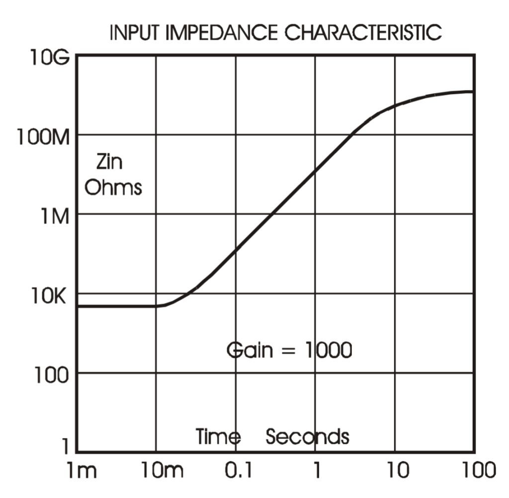
The EM A10 is a low level amplifier module for sensitive measurements, data collection and systems, where signals below 1 nanovolt may be measured. It is ideal for the input unit for precision voltage measuring systems, requiring voltage sensitivity for measuring low noise and low impedance sources. The noise level of the A10 is equivalent to a perfect resistor of about 20Ω. When used with a digital voltmeter, steady one nanovolt digits may be displayed, with a response time constant of less than a second. The input voltage stability of the A10 is very high, with the drift around a nanovolt per degree C. The input connectors are made from pure copper. The input impedance is very high, and is time dependent, determined by the loop gain.
The very high D.C. gain of greater than five by ten to the power twelve means that high overall gain may be used, controlled precisely by feedback resistors, thus ensuring a good degree of linearity with the accuracy defined by the feedback resistors used. Despite the gain, the A10 is stable with 100% feedback. This allows a filter capacitor to be used across the feedback resistor to control the rise time and noise from the measurement circuit. The loop gain is reduced from the DC figure of 5e12 at the rate of 30 dB per frequency decade to unity at 20KHz. This determines the response time of the amplifier, which will vary according to the set gain.
The A10 can deliver 2 milliamps of current from its output and so the set gain will determine the level of output signal at low values of gain less than 1,500. The internal ‘low’ feedback resistor is 1 ohm, and so if a gain of unity is set by connecting the output to the feedback terminal directly, the maximum output voltage will be 2 millivolts. The internal feedback resistor needs to be this low, because the noise generated by this resistor is in series with the input noise, and any higher resistance would cause a significant increase in the total A10 noise.
The power consumption is very low, making the A10 suitable for battery powered applications. The nominal supply voltage is plus and minus 6 volts, and the quiescent current consumption is only 1.5 milliamps. Care is required over the choice of power supply, if batteries are not to be used, to ensure that the very low noise of the A10 is not degraded by series mode or common mode noise which may interfere with small signals. The A10 has very high rejection of common mode noise, but at nanovolt levels great care must be taken.
The A10 is small enough to mount on a p.c. board if required, and the case is made of Mumetal to give an extra degree of magnetic and electrostatic screening. The voltage and current offset controls are accessible with small insulated trimming tool through the two holes in the front. Care should be taken with these adjustments.
- SPECIFICATION
Specification: DC Nanovolt Amplifier Model A10
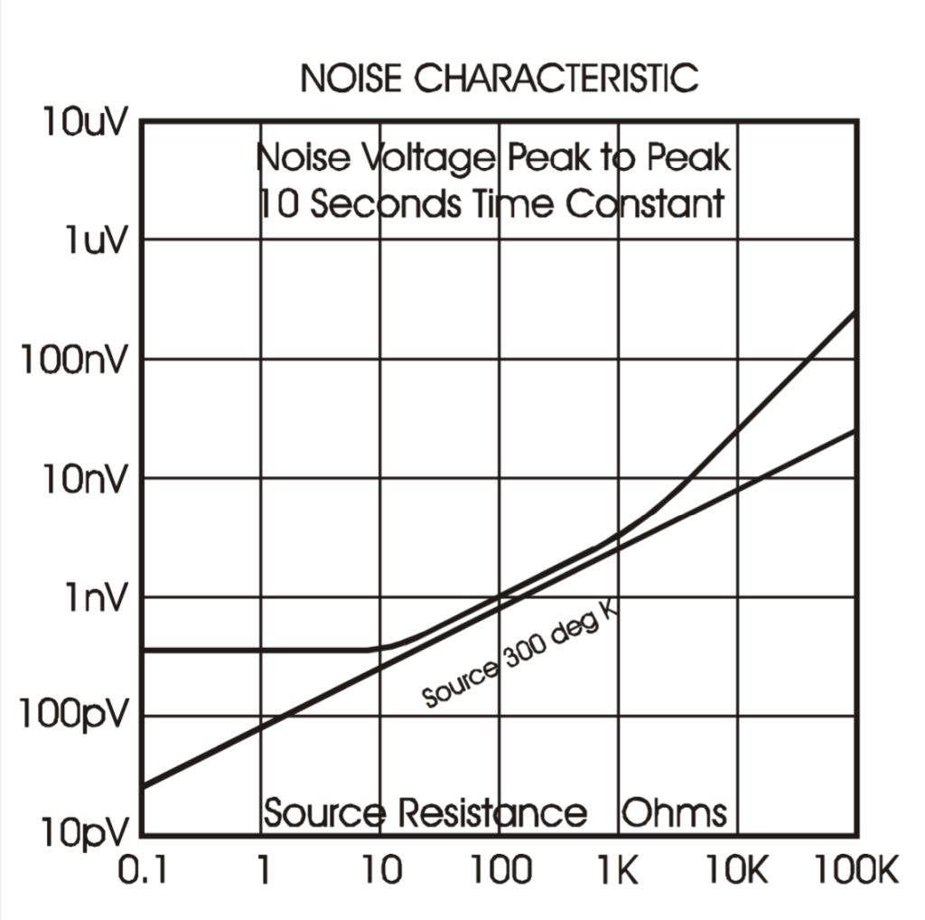
Noise
Equivalent noise resistance is typically 20Ω. Noise voltage depends on bandwidth, e.g. rise time constant 1 second gives a peak to peak noise voltage of 1 nanovolt. There is no 1/f component.Offset Voltage
Adjustable to zero. T.C. typically 1nV per degree COffset Current
Adjustable to zero. T.C. better than 5pA per degree C.Gain and Bandwidth
Greater than 5e12 at DC reducing to unity at 20 K Hz. Amplifier gain is set using an external feedback resistor. The fixed internal feedback component is 1Ω + / – 1% 5 ppm, so for a gain of 10,000, the feedback element must be 9999Ω.Input Resistance
Greater than 1GΩ, with gain set to 1 million or less, subject to time following an input step function.Source Resistance
The A10 closely follows the source Johnson noise characteristic from source resistance of 20Ω up to approaching 20 K ohms.
With source resistances below 20Ω the noise is substantially constant down to zero ohms.Input Level
The A10 will operate with input voltages up to + / – 2mV.Output Level
The A10 will provide an output up to + / – 3V D.C. at 2mA load, including the current taken by the feedback resistor.Connectors
The input connectors are 3mm studs and nuts in pure copper. All other connectors are M3 brass studs and nuts.Power Supply
Minimum + / – 5.5V at 2mA. Maximum + / – 12V. Nominal Supply +/- 6 volts.Dimensions and Weight
Length 120mm. Width 70mm. Height 35mm. + 6mm for terminals. Weight 540gm.Fixing
4 Holes required 3mm diameter. 114mm X 54mm.Note. Feedback Components.
There is an internal feedback resistor from the ‘Feedback’ terminal to the input ‘Lo’ of 1 ohm + / – 1% 5 ppm/degree C. The gain is set by connecting an external resistor from ‘Output’ to ‘Feedback’ . The value of this resistor is Rfb = (gain required – 1) Ω. i.e. Gain = 10,000, Rfb = 9999Ω. As the internal feedback resistor has a tolerance of 1%, the external feedback resistor needs to be adjusted by +/- 1%. the gain stability will be 5ppm per degree C plus the stability of the applied feedback resistor.There is a 10pF capacitor connected from ‘Output’ to ‘Feedback’
- GRAPHS